
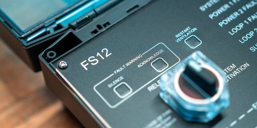
FS12 - User manual
1. Preface
This document is the user manual for the FS12 – Control and Monitoring System for Fixed Aerosol Fire Extinguishing Systems.
1.1 Purpose
The purpose of this document is to describe in short terms the use of the FS12 system. Installation and service is described in the FS12 Installation Manual.
2. System description
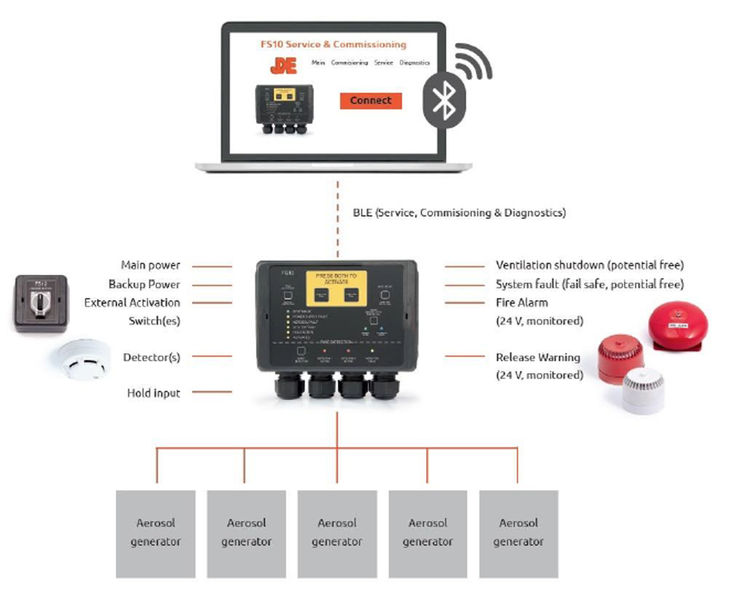
The purpose of the FS12 system is to control and monitor a number of aerosol generators mounted on a ship as part of a fire extinguishing systems. The primary purpose of the FS12 system is to activate the aerosol generators in event of fire. The secondary purpose of the FS12 system is to monitor the system itself (e.g. power supplies, cables and individual system components) and give an alarm if a fault within the system is detected. Furthermore, an input is provided for smoke detectors.
3. Front panel
The front panel of the FS12 main unit is shown below:
3.1 Indicators and buttons
- OK indicator
The OK indicator (green) is lit under normal operation. Note that under all circumstances at least one indicator on the FS12 front panel must be lit. Please consult the FS12 Installation Manual for further details. - Fault indicators
If a fault condition is detected by the FS12 system, the corresponding fault indicator (red) will be lit. - Release indicator
The Release indicator (orange) will be flashing in the activation delay period and will be permanently lit when aerosols have been released. - Fire alarm indicator
The Fire alarm indicator will be lit if fire or smoke is detected by detector(s) connected to the FS12 system. - Ventilation button
When activating the release of the aerosol generators, the ventilation in the protected area will be shut off. After extinction of the fire, the ventilation may be turned on again by pressing the Restart Ventilation button. - Fault handling buttons
If a fault is detected, the corresponding indicator is lit, and the internal buzzer and external fault warning device is turned on (if connected). By pressing the Fault Warning Silence button, the internal buzzer may be turned off. When the fault condition has been remedied, the fault indicator and the external fault warning device may also be turned off by pressing the Fault Warning Acknowledge button. Pressing the Acknowledge button also resets the fault condition. If the fault condition is still present, pressing the Acknowledge button has no effect. - Release button
In event of fire lift the cover and turn the Release button clockwise to activate the aerosol generators. Note that the aerosol generators will be activated even if the Release button is turned back (counter clockwise). - Fire alarm buttons
If fire or smoke is detected by detector(s) connected to the FS12 system, the Fire alarm indicator is lit, and the internal buzzer and external fire alarm device is turned on. By pressing the Fire Alarm Silence button, the internal buzzer and the external fire alarm device may be turned off. When the fire or smoke is no longer present, the fire alarm may be reset by pressing the Fire Alarm Acknowledge button. Pressing the Acknowledge button also resets the fire alarm. If the fire alarm is still present, pressing the Acknowledge button has no effect. - Internal buzze
The internal buzzer is turned on when a fault condition or smoke or fire is detected. It will also be bleeping when release of aerosol generators has been activated.
4. Activating the aerosol generators
- Flip the Release button cover (7).
- Turn the Release button (7) clockwise. Note that the aerosol generators will be activated even if the Release button is turned back (counter clockwise).
- The ventilation in the protected area is turned off.
- The activation delay time elapses. (20s-120s, set during installation depending on size of the protected area). During this time the external release warning device is turned on, the internal buzzer (9) is bleeping and the Release indicator (3) is flashing.
- The aerosol generators are activated. (Taking up to 25s depending on number of aerosol generators).
- After activation the internal buzzer (9) and the Release indicator (3) are turned on permanently. The internal buzzer may be turned off by pressing the Silence Fault Warning button (6).
- After complete extinction of fire, the ventilation in the protected area may be restarted by pressing the Restart Ventilation button (5).
5. Fault handling
- If a fault condition is detected, the corresponding fault indicator (2), the internal buzzer (9) and external fault warning device (if connected) is turned on.
- The internal buzzer (9) and external fault warning device may be turned off by pressing the Silence Fault Warning button (6).
- For further details regarding faults and troubleshooting, please refer to the installation manual.
- When the fault condition has been remedied, the fault indicator may be turned off by pressing the Acknowledge Fault Warning button (6).
6. Fire alarm handling
Please notice that an active Fire alarm will not automatically lead to activation of the aerosol generators. In all cases this must be done as described in chapter 4.
- If fire or smoke is detected by detector(s) connected to the FS12 system, the Fire alarm indicator is lit, and the internal buzzer and external fire alarm device is turned on.
- The internal buzzer (9) and external fire alarm device may be turned off by pressing the Silence Fire Alarm button (8).
- If deemed necessary, the aerosol generators may be released to extinguish the fire as described above.
- When the fire or smoke is no longer present, the fire alarm may be reset by pressing the Fire Alarm Acknowledge button (8).
- The Detector fault indicator (2) will be lit shortly while the connected detector(s) are being reset.
